Andrei Shirobokov
Chief Technology Officer
DeepSpar Data Recovery Systems
http://www.deepspar.com
Abstract
Many data recovery professionals are not taking full advantage of
disk imaging, the second phase in the 3D Data Recovery process. Traditional disk
imaging methods are time-consuming and don’t always yield usable data, because of
read instability and the constraints of system software. DeepSpar Disk Imager overcomes
these challenges, efficiently retrieving data from bad sectors and reducing the
risk of disk failure. Data recovery firms can handle more cases and retrieve more
data by going deeper during this data recovery phase.
Introduction
Data recovery firms are missing out on data they could
retrieve with the complete 3D Data Recovery process. Proper data recovery involves
three phases: drive restoration, disk imaging, and data retrieval. But data recovery
professionals can face frustrating problems when imaging a damaged disk. The drive
may repeatedly stop responding in the middle of copying data. The drive may fail
completely because of the stress caused by intensive read processes. Significant
portions of data may be left behind in bad sectors.
These issues plague firms that use traditional disk
imaging methods. Read instability makes it difficult to obtain consistent data quickly,
and system software is not equipped to read bad sectors. However, these problems
can be solved with imaging tools that address disk-level issues.
Imaging software bypasses system software and ignores
error correction code (ECC), processing each byte of data in bad sectors. Inconsistent
data is evaluated statistically to determine the most likely correct value. Faster
transfer methods speed up the process, and customizable algorithms allow the data
recovery professional to fine-tune each pass. Imaging software provides feedback
on the data recovered while imaging is still underway.
Imaging hardware can reset the drive when it stops responding,
which minimizes damage from head-clicks and allows the process to run safely without
supervision.
DeepSpar Disk Imager incorporates all of these methods, enabling firms
to recover more data from previously inaccessible drives, and significantly reducing
the imaging time required.
1. About the 3D Data Recovery Process
A complete data recovery process includes these three phases:
- Drive Restoration:
Damage to the hard disk drive (also referred to as
HDD) is diagnosed and repaired as necessary, using a product such as PC-3000 Drive
Restoration System by ACE Laboratory Russia. There are three main types of damage:
- Physical/mechanical damage: Failed heads and other physical problems are often repaired by replacing the damaged hardware with a donor part.
- Electronic problems:Failed printed circuit boards (PCBs) are replaced with donor PCBs, and the contents of the failed PCB read-only memory (ROM) are copied to the donor.
- Firmware failure: Firmware failures are diagnosed and fixed at the drive level.
- Disk Imaging: The contents of the repaired drive are read and copied to another disk, using a
product such as DeepSpar Disk Imager. Disk imaging prevents further data loss caused by working
with an unstable drive during the subsequent data retrieval phase.
Drives presented for recovery often have relatively minor physical degradation due to wear from
normal use. The wear is severe enough for the drive to stop working in its native system. However,
imaging software can work with slightly degraded drives, so part replacement is often not required.
In these cases, the data recovery process can skip drive restoration and start with disk imaging.
- Data Retrieval: The original files that were copied onto the image drive are retrieved. Data retrieval can involve these tasks:
- File system recovery: The recreation of a corrupted file system structure such as a
corrupted directory structure or boot sector, due to data loss. This task is accomplished by using a product such as PC-3000 Data Extractor by ACE Laboratory Russia.
- File verification: Recovered files are tested for potential corruption. DeepSpar provides
a file verification tool for this task which generates a report that can be delivered to the client.
- File repair: If necessary, corrupted files are repaired. Files might be corrupt because data
could not be fully restored in previous phases, in which case disk imaging is repeated to
retrieve more sectors. File repair is completed, where possible, using vendor-specific tools.
Drive restoration and data retrieval, the first and last phases, are well-serviced by the data recovery industry.
Many data recovery companies have the necessary software, hardware, knowledge, and skilled labour to complete
these phases. However, the technology for effective disk imaging has been relatively neglected because of its challenges,
making it a weak link in the data recovery process. Data recovery firms that skim the surface with traditional imaging
methods often miss out on potential revenue.
2. Problems with Disk Imaging
Disk imaging is not a trivial task. Degraded drives and drives whose physical defects have been repaired often yield a high
read error rate, or read instability. Read instability means that multiple readings of the same data tend to yield different
results each time. Read instability differs from cases where data originally written in error is read consistently each time,
or where a physical scratch makes an entire part of the disk unreadable no matter how many read attempts are made.
What Causes Read Instability?
Repaired drives may have high read instability for a number of reasons. Donor parts, while nominally identical to the original
failed parts, differ slightly due to tolerances in the manufacturing process. The majority of modern hard disk drives are
individually tested at the factory and have optimized adaptive parameters burned into the read-only memory. If one or more
parts are later replaced, the adaptive parameters are no longer optimized to the new configuration. Because modern drives are
fine-tuned to obtain maximum performance and capacity, even small deviations from optimum can introduce a high rate of
read errors.
In drives that have not been repaired, physical degradation due to normal use also means that adaptive parameters are no longer
optimum, thus leading to read instability. For example, wear in the actuator bearings causes slight deviations in the distance the
arm moves across the platter. As a result, the current that was once required to move the actuator to a certain track is no longer
sufficient to move the arm precisely. Read errors can also be caused by dust infiltration into the disk drive over the course of its
life, which may make the read process electronically noisy.
The important point is that failed drives tend to have read instability no matter what the reason for failure.
For the purposes of imaging a disk, read instability is not a major obstacle in principle, since each sector can be read several
times and statistical methods can be applied to obtain the most likely correct value for each byte. However, because of the way
that the basic input/output system (BIOS), operating system (OS), and drive firmware behave, it is impossible to obtain data during
drive read instability without specialized hardware and software.
Why System Software Can’t Handle Read Instability
System software consists of a computer’s BIOS and OS. The primary reason that computers can’t handle read instability
without specialized tools is that the system software reads each disk sector presuming that the sector is not corrupted—that is,
that the data is read-stable. A sector on a disk typically consists of a header, 512 bytes of data, and error correction code (ECC)
bytes (Figure 1). Other bytes are present to facilitate read/write synchronization.
For simplicity, the ECC bytes can be thought of as a checksum to validate data integrity. Most current hard disk drives are
Advanced Technology Attachment (ATA) compliant devices. The system software reads the drive sector-by-sector, using the
standard ATA read sector command. If a sector has a wrong ECC checksum, it returns no data, just an error, despite the fact that
most of the bytes in the sector are likely correct and all are actually readable, even if some of the data is corrupt. The system
software is unable to access data byte-by-byte, using other ATA read commands that read data regardless of ECC status.
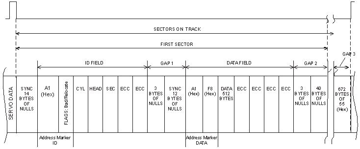 Figure 1: Example of Sector Format.
The system software reads drives in this way because the mandate of computer architecture is to create a reliable, stable
machine that runs at the highest possible speed. The system software cannot allow errors to be propagated from the hard drive
to the computer’s random access memory (RAM). These errors might be part of an executable file that would then cause the
computer to stop responding. Thus, system software has a low tolerance for read instability, and assumes that the drive is working
correctly without delving into drive errors except to flag whole sectors as bad and to avoid reading them.
Also, in many cases the system software is unable to handle drive errors, a situation that may cause the system to stop responding.
Using the system software to read a drive is also time-consuming and involves intense drive processing, leading to further wear.
This wear increases the likelihood of further disk degradation during the imaging process. See “Processing All Bytes in Sectors with
Errors ” for more information on how disk imaging is by its nature very demanding on the drive, involving multiple reads on the
entire disk and modifying its firmware data. Since progressive disk degradation is common (that is, read instability increases with use),
it is desirable to reduce the demands on the drive.
Thus, even a relatively low level of read instability, which is common for drives in recovery, can lead to the computer not being
able to read the drive at all, despite the fact that the drive is still readable by other means.
3. Solving Disk Imaging Problems
Imaging tools provide custom hardware and software solutions to the challenges of read instability.
Processing All Bytes in Sectors with Errors
While the system software works well with hard disk drives that are performing correctly, read instability must be dealt with using
specialized software that bypasses the BIOS and operating system. This specialized software must be able to use ATA read commands
that ignore ECC status. (These commands are only present in the ATA specification for LBA28 mode, though, and are not supported
in LBA48.) Also, the software should have the capability of reading the drive error register (Figure 2), which the standard system
software doesn’t provide access to. Reading the error register allows specialized software to employ different algorithms for different
errors. For instance, in the case of the UNC error (“Uncorrectable Data: ECC error in data field, which could not be corrected”), the
software can issue a read command that ignores ECC status. In many cases, the AMNF error can be dealt with in a similar way.
 Figure 2: ATA Error Register.
Bit 0 - Data Address Mark Not Found: During the read sector command, a data address mark was not
found after finding the correct ID field for the requested sector (usually a media error or read instability).
Bit 1 - Track 0 Not Found: Track 0 was not found during drive recalibration.
Bit 2 - Aborted Command: The requested command was aborted due to a device status error.
Bit 3 - Not used (0).
Bit 4 - ID Not Found: The required cylinder, head, and sector could not be found, or an ECC error occurred in the ID field.
Bit 5 - Not used (0).
Bit 6 - Uncorrectable Data: An ECC error in the data field could not be corrected (a media error or read instability).
Bit 7 - Bad Mark Block: A bad sector mark was found in the ID field of the sector or an Interface CRC error occurred.
Figure 2: ATA Error Register.
Bit 0 - Data Address Mark Not Found: During the read sector command, a data address mark was not
found after finding the correct ID field for the requested sector (usually a media error or read instability).
Bit 1 - Track 0 Not Found: Track 0 was not found during drive recalibration.
Bit 2 - Aborted Command: The requested command was aborted due to a device status error.
Bit 3 - Not used (0).
Bit 4 - ID Not Found: The required cylinder, head, and sector could not be found, or an ECC error occurred in the ID field.
Bit 5 - Not used (0).
Bit 6 - Uncorrectable Data: An ECC error in the data field could not be corrected (a media error or read instability).
Bit 7 - Bad Mark Block: A bad sector mark was found in the ID field of the sector or an Interface CRC error occurred.
Only when the sector header has been corrupted (an IDNF error) is it unlikely that the sector can be read, since the drive in this
case is unable to find the sector. Experience shows, however, that over 90 percent of all problems with sectors are due to errors
in the data, not in the header, because the data constitutes the largest portion of the sector. Also, the data area is constantly being
rewritten, which increases read instability. Header contents usually stay constant throughout the life of the drive. As a result, over
90 percent of sectors that are unreadable by ordinary means are in fact still readable. Moreover, problem sectors usually have a
small number of bytes with errors, and these errors can often be corrected by a combination of multiple reads and statistical methods.
If a sector is read ten times and a particular byte returns the same value eight times out of ten, then that value is statistically likely to
be the correct one. More sophisticated statistical techniques can also be useful.
In fact, DeepSpar has encountered situations in which every sector of a damaged drive had a problem. This situation would normally
leave the data totally unrecoverable, but with proper disk imaging, these drives were read and corrected in their entirety.
Unfortunately, most imaging tools currently available on the market use system software to access the drive and are therefore extremely
limited in their imaging capabilities. These products attempt to read a sector several times in the hope that one read attempt will complete
without an ECC error. But this approach is not very successful. For example, if there is even a one percent chance of any byte being read
incorrectly, the chances of reading all 512 bytes correctly on one particular read is low (about 0.58 percent). In this case, an average of
170 read attempts would be necessary to yield one successful sector read. As read instability increases, the chances of a successful read quickly
become very low. For example, if there were a ten percent chance of reading any byte wrong, an average of 2.7 x 10²³ read attempts would
be needed for one successful one. If one read attempt took 1 ms, this number of reads would take 8000 billion years, or many times the age
of the universe. No practical number of read attempts will give a realistic chance of success.
However, if imaging software can read while ignoring ECC status, a 10 percent probability of a byte being read in error is not an issue. In
10 reads, very few bytes will return less than seven or eight consistent values, making it virtually certain that this value is the correct one.
Thus, imaging software that bypasses the system software can deal with read instability much more easily.
Disabling Auto-Relocation and SMART Attribute Processing
While the methods outlined in the previous section go a long way to obtaining an image of the data, other problems remain.
When drive firmware identifies a bad sector, it may remap the sector to a reserved area on the disk that is hidden from the user (Figure 3).
This remapping is recorded in the drive defects table (G-list). Since the bad sector could not be read, the data residing in the substitute sector
in the reserved area is not the original data. It might be null data or some other data in accordance with the vendor-specific firmware policy,
or even previously remapped data in the case where the G-list was modified due to corruption.
Moreover, system software is unaware of the remapping process. When the drive is asked to retrieve data from a sector identified as bad,
the drive firmware may automatically redirect the request to the alternate sector in the reserved area, without notifying the system before the
error is returned. This redirection occurs despite the fact that the bad sector is likely still readable and only contains a small number of bytes
with errors.
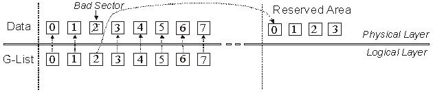 Figure 3: G-List Remapping.
This process performed by drive firmware is known as bad sector auto-relocation. This process can and should be turned off before the imaging
process begins. Auto-relocation on a drive with read instability not only obscures instances when non-original data is being read, it is also
time-consuming and increases drive wear, possibly leading to increased read instability.
Effective imaging software should be able to turn off auto-relocation so that it can identify problem sectors for itself and take appropriate action,
` which ensures that the original data is being read.
Unfortunately, the ATA specification does not have a command to turn off auto-relocation. Therefore imaging software should use vendor-specific
ATA commands to do this.
A similar problem exists with Self-Monitoring Analysis and Reporting Technology (SMART) attributes. The drive firmware constantly recalculates
SMART attributes and this processing creates a large amount of overhead that increases imaging time and the possibility of further drive degradation.
Imaging software should be able to disable SMART attribute processing.
Other drive preconfiguration issues exist, but auto-relocation and SMART attributes are among the most important that imaging software should address.
Increasing Transfer Speed with UDMA Mode
Modern computers are equipped with drives and ATA controllers that are capable of the Ultra Direct Memory Access (UDMA) mode of data transfer.
With Direct Memory Access (DMA), the processor is freed from the task of data transfers to and from memory. UDMA can be thought of as an advanced
DMA mode, and is defined as data transfer occurring on both the rise and fall of the clock pulse, thus doubling the transfer speed compared to ordinary DMA.
Both DMA and UDMA modes are in contrast to the earlier Programmed Input Output (PIO) mode in which the processor must perform the data transfer itself.
Faster UDMA modes also require an 80-pin connector, instead of the 40-pin connector required for slower UDMA and DMA.
The advantages are obvious. Not only does UDMA speed up data transfer, but the processor is free to perform other tasks.
While modern system software is capable of using UDMA, imaging software should be able to use this data transfer mode on a hardware-level
(bypassing system software) as well. If the source and destination drives are on separate IDE channels, read and write transfers can occur simultaneously,
doubling the speed of the imaging process. Also, with the computer processor free, imaged data can be processed on the fly. These two advantages can only
be achieved if the imaging software handles DMA/UDMA modes, bypassing system software. Most imaging tools currently available on the market use
system software to access the drive and so don’t have these advantages.
Customizing Imaging Algorithms
Consider the following conflicting factors involved in disk imaging:
- A high number of read operations on a failed drive increase the chances of recovering all the data, and decrease the number of probable errors in that data.
- Intensive read operations increase the rate of disk degradation and increase the chance of catastrophic drive failure during the imaging process.
- Imaging a drive can take a long time (for example, one to two weeks) depending on the intensity of the read operations. Customers with
time-sensitive needs may prefer to rebuild data themselves rather than wait for recovered data.
Clearly these points suggest the idea of an imaging algorithm that maximizes the probable data recovered for a given total read activity, taking into
account the rate of disk degradation and the probability of catastrophic drive failure. However, no universal algorithm exists. A good imaging procedure
depends on such things as the nature of the drive problem, and the characteristics of the vendor-specific drive firmware. Moreover, a client is often
interested in a small number of files on a drive and is willing to sacrifice the others to maximize the possibility of recovering those few files. To meet
these concerns, the judgement of the imaging tool operator comes into play.
Drive imaging can consist of multiple read passes. A pass is one attempt to read the entire drive, although problem sectors may be read several times
on a pass or not at all, depending on the configuration. The conflicting considerations mentioned above suggest that different algorithms, or at least
different parameter values, should be used on each pass.
The first pass could be configured to read only error-free sectors. There is a fair possibility that the important files can be recovered faster in this
way in just one pass. Moreover, this pass will not be read-intensive since only good sectors are read and the more intensive multiple reads needed
to read problem sectors are avoided. This configuration reduces the chances of degrading the disk further during the pass (including the chances of
catastrophic drive failure) while having a good chance at recovering much of the data.
Second and subsequent passes can then incrementally intensify the read processes, with the knowledge that the easily-readable data have already
been imaged and are safe. For instance, the second pass may attempt multiple reads of sectors with the UNC or AMNF error (Figure 2). Sectors
with the IDNF error are a less promising case, since the header could not be read and hence the sector could not be found. However, even in this
case multiple attempts at reading the header might result in a success, leading to the data being read. Successful data recovery of sectors with
different errors depends on the drive vendor. For example, drives from some vendors have a good recovery rate with sectors with the IDNF error,
while others have virtually no recovery. Prior experience comes into play here, and the software should be configurable to allow different read
commands and a varying number of reread attempts after encountering a specific error (UNC, AMNF, IDNF, or ABRT).
Drive firmware often has vendor-specific error-handling routines of its own that cannot be accessed directly by the system. While you may
want to minimize drive activity to speed up imaging and prevent further degradation, drive firmware increases that activity and slows down
the process when faced with read instability. To minimize drive activity, imaging software must implement a sector read timeout, which is a
user-specified time before a reset command is sent to the drive to stop processing the current sector.
For example, you notice that good sectors are read in 10 ms. If this is a first pass, and your policy is to skip problem sectors at this point,
the read timeout value might be 20 ms. If 20 ms have elapsed and the data has not yet been read, the sector is clearly corrupted in one way
or another and the drive firmware has invoked its own error-handling routines. In other words, a sector read timeout can be used to identify
problem sectors. If the read timeout is reached, the imaging software notes the sector and sends a reset command. After the drive cancels
reading the current sector, the read process continues at the next sector.
By noting the sectors that timeout, the software can build up a map of problem sectors. The imaging algorithm can use this information during subsequent read passes.
In all cases the following parameters should be configurable:
- Type of sectors read during this pass
- Type of read command to apply to a sector
- Number of read attempts
- Number of sectors read per block
- Sector read timeout value
- Drive ready timeout value
- Error-handling algorithm for problem sectors
Other parameters may also be configurable but this list identifies the most critical ones.
Imaging Hardware Minimizes Damage
In addition to the software described above, data recovery professionals also need specialized hardware to perform imaging in the
presence of read instability. Drive firmware is often unstable in the presence of read instability, which may cause the drive to stop responding.
To resolve this issue, the imaging system must have the ability to control the IDE reset line if the drive becomes unresponsive to software commands.
Since modern computers are equipped with ATA controllers that do not have ability to control the IDE reset line, this functionality must be implemented
with a specialized hardware. In cases where a drive does not even respond to a hardware reset, the hardware should also be able to repower
the drive to facilitate a reset.
If the system software cannot deal with an unresponsive hard drive, it will also stop responding, requiring you to perform a manual reboot
of the system each time in order to continue the imaging process. This issue is another reason for the imaging software to bypass the system software.
Both of these reset methods must be implemented by hardware but should be under software control. They could be activated by a
drive ready timeout. Under normal circumstances the read timeout sends a software reset command to the drive as necessary. If this procedure fails and
the drive ready timeout value is reached, the software directs the hardware to send a hardware reset, or to repower the drive. A software reset is least taxing
on the disk drive and the repower method is most taxing. A software reset minimizes drive activity while reading problem sectors, which reduces
additional wear. A hardware reset or the repower method deals with an unresponsive hard drive.
Moreover, because reset methods are under software control via the user-configurable timeouts, the process is faster and there is no need for constant user supervision.
The drive ready timeout can also reduce the chances of drive self-destruction due to head-clicks, which is a major danger in drives with read instability.
Head-clicks are essentially a firmware exception in which repeated improper head motion occurs, usually of large amplitude leading to rapid drive self-destruction.
Head-clicks render the drive unresponsive and thus the drive ready timeout is reached and the software shuts the drive down, hopefully before damage has occurred.
A useful addition to an imaging tool is the ability to detect head-clicks directly, so it can power down the drive immediately without waiting for a timeout,
thus virtually eliminating the chances of drive loss.
4. DeepSpar Disk Imager
Clearly, many factors need to be taken into consideration if an imaging tool is to approach the maximum possible imaging effectiveness
using current technology. DeepSpar Disk Imager successfully incorporates all the functionality described thus far, and also incorporates additional
features that further enhance its performance.
DeepSpar Disk Imager Architecture
Figure 4 shows a schematic of the product system configuration. The host system can be any modern computer, or even just a motherboard
with a keyboard and a monitor. The DeepSpar Disk Imager hardware module sits between the source drive and the host computer. A single IDE
cable connects the host computer, the hardware module, and the source drive. The system boots with the DeepSpar Disk Imager software from
the flash memory of the hardware module. The interconnection of the DeepSpar Disk Imager hardware module allows it to send hardware resets
and repower the source drive without resetting the entire system.
 Figure 4: System architecture. A single IDE cable connects the computer, the DeepSpar Disk Imager hardware, and the source drive.
The imaging software is written in assembly language, bypassing the system software. This approach was chosen for its low overhead and high
performance, and also reduces the load on the drive. The software addresses all issues discussed earlier:
- Preconfigures the drive
- Implements sector read and drive ready timeouts
- Bypasses system software
- Uses UDMA mode with simultaneous (overlapped) read/write operations. In this mode, disk imaging speed can come close to the drive
maximum read access speed—that is, the speed of a surface verification.
- Runs efficiently while unsupervised, with minimal risk of drive self-destruction
- Uses a flexible algorithm with many configurable parameters to customize the process based on prior experience, and the needs of each particular job
 Figure 5: A DeepSpar Disk Imager dialog box showing configurable parameters of the imaging algorithm. The user can select various event-action scenarios.
Destination Drive Stores All Information
In addition to the features mentioned, the product is configured to write all important information about the imaging process to the destination drive:
- Configuration parameters
- Map of sectors already read or attempted, along with error type, if any
- State of the imaging process
- Information about the source drive
This method of information management has several advantages. The image map ensures that, on subsequent passes, DeepSpar Disk Imager focuses
its processes on sectors that were not successfully read during initial passes. The information and the map are updated dynamically so that if the imaging
process is interrupted for any reason, the process can be restarted where it left off without any loss of information. With all information in one place,
you do not need to keep other records of a particular job, such as information about the source drive, the client’s order number, and a map of all problem sectors.
This feature may be useful if another, higher priority job arrives. Work on the current job can be interrupted without any extra effort, and continued
again at any time in the future with no loss of imaged data or the associated information. Also, if a system power failure occurs, imaging can
pick up where it left off once power is restored.
Configuration information and the image map written to the destination hard drive create an overhead of about two percent of the data, so the destination
drive should be larger than the source drive.
UDMA Enables Processor to Process Data on the Fly
Since DeepSpar Disk Imager uses UDMA with overlapped read/write operations, a typical data transfer rate for modern drives usually reaches up to
60 MB/s (about 3.6 GB/min) and for some drives may reach up to 75 MB/s (about 4.5 GB/min). This transfer method greatly speeds up the imaging process.
Also, it leaves the processor free to perform other tasks during imaging. For example, DeepSpar Disk Imager displays information about imaged data on the
screen on the fly. Figure 6 shows a typical information page displayed during imaging.
The status of recently read sectors appears in the top portion of the screen. This information tells you the success rate of the read process with the current
set of parameters. You can change the parameters as necessary during the imaging process based on this information.
The sector contents appear in the middle of the screen for each sector on the fly. This information lets you know whether actual user data is being imaged,
or whether the data is just an array of nulls, for example. With other imaging tools, the operator doesn’t know the contents of the imaged data until imaging
is complete. In these cases, the time and resources invested in imaging may be for nothing. Data recovery firms are particularly sensitive to this problem since
most client arrangements are on a no data, no fee basis. So data evaluation on the fly is a distinct advantage. With DeepSpar Disk Imager, if the current sectors
contain no user data, the operator can skip ahead and try another part of the disk.
Finally, while the imaging process is underway, DeepSpar Disk Imager also identifies file system structure elements (FAT and NTFS), and the files of known
types. This information appears in the bottom status bar (Figure 6), thus further enhancing data evaluation functionality.
Note that using the processor to provide information on the fly this way does not slow down the imaging process, since data transfer is handled by a UDMA
controller and not the processor. There is no speed trade-off for having all this information available on the fly.
 Figure 6: Typical main screen during the imaging process. The top status bar shows the status of recently accessed sectors: read successfully,
skipped, and errors, if any. Contents of sectors are shown on the fly. The bottom status bar shows the number of files of various types and operating
system structure elements imaged so far: executable files, Microsoft Office files, pictures, file system elements.
Figure 6: Typical main screen during the imaging process. The top status bar shows the status of recently accessed sectors: read successfully,
skipped, and errors, if any. Contents of sectors are shown on the fly. The bottom status bar shows the number of files of various types and operating
system structure elements imaged so far: executable files, Microsoft Office files, pictures, file system elements.
With the features described above, DeepSpar Disk Imager addresses all the basic problems of traditional disk imaging methods.
5. Conclusion
A successful data recovery depends on the effectiveness of the data imaging tool. As this paper has shown, many factors must be taken into account
if an imaging tool is to provide the maximum performance possible with current technology. However, very few of these factors have been incorporated
into the imaging tools currently available on the market. Given the prevailing no data, no fee arrangement, failures in data imaging, which might not be
revealed until the process is complete, are an economic problem for recovery firms. Moreover, the length of time taken to recover data is often critical
to a client, and a firm unable to image quickly is at a disadvantage.
DeepSpar Disk Imager incorporates all useful methods that are possible with current technology. Compared with competing products, DeepSpar Disk Imager
is much faster, is more likely to retrieve data if it indeed exists, and has a much lower risk of catastrophic drive failure. Unlike other products, DeepSpar Disk
Imager can run safely without operator supervision, and allows for data assessment on the fly. Firms that add DeepSpar Disk Imager to their data recovery
toolbox will find the investment pays for itself very quickly, in higher revenues and satisfied clients.
©2004-2010 ACE Data Recovery Engineering Inc.
DeepSpar, DeepSpar Disk Imager,
3D Data Recovery, and all associated designs are trademarks of ACE Data Recovery Engineering Inc.
PC-3000 and Data Extractor are products of ACE Laboratory
Russia, sold under contract in
North America by ACE Data Recovery Engineering Inc. under the DeepSpar brand.